
Website owner: James Miller
Ballistic galvanometer. Galvanometer damping. Search coil method of measuring magnetic flux. Permeability. Magnetization curve. Rowland ring. Hysteresis. Curie temperature. Ampere’s theory of magnetism. Magnetic circuit.
Def. Ballistic galvanometer. A galvanometer specially designed to measure the quantity of charge displaced in a current of short duration (such as in the charging or discharging of a capacitor). It can be shown that the deflection of the coil is proportional to the quantity of charge passing through it. It is typically a sensitive moving-coil mirror galvanometer with a coil that has a relatively large moment of inertia and a long period of vibration as compared with a galvanometer designed for current measurement.
When a short burst of current passes through the galvanometer, there is very little rotation of the galvanometer coil until after the current has ceased. An angular impulse is delivered to the coil that is proportional to the quantity of charge q = ∫Idt that passed through. The angular impulse depends on the torque, which is proportional to the current, and upon the time interval during which the torque is applied. This angular impulse delivered to the coil produces an equal angular momentum of the coil. The coil then proceeds to swing until its initial kinetic energy has been converted to potential energy of the suspension. The process is completely analogous to what takes place when a ballistic pendulum is struck by a bullet.
Galvanometer damping. A ballistic galvanometer will oscillate if it has not been properly damped. Galvanometers are damped by adding a shunt resistor of just the right amount of resistance in parallel with them. The proper amount of resistance at which the motion just ceases to be oscillatory is called the critical external damping resistance (CXDR). When shunted by its CXDR, the galvanometer is said to be critically damped. With more resistance it is underdamped and with less it is overdamped. When the galvanometer is critically damped, it will make one swing and return slowly to its zero position.
Search coil method of measuring magnetic flux. The flux density in a magnetic field can be measured using a small flat coil of fine insulated wire with a large number of turns called a search coil or snatch coil. A search coil may be 0.5 cm in diameter and have 500 to 2000 turns. It is mounted on a long insulated handle. Using the coil to determine magnetic flux density involves connecting the coil to a ballistic galvanometer and placing the coil in the field to be measured with the plane of the coil perpendicular to the direction of the flux field., then quickly pulling the coil out of the field to a position where the field intensity is zero and noting the galvanometer reading. As the turns of the coil cut through lines of flux, a transient current is produced causing a galvanometer deflection..
When the coil is in the flux field, the amount of flux passing through the coil is given by Φ = BA, where A is the area enclosed by the coil. After the coil is removed from the field, the amount of flux passing through the coil is zero. Thus when the coil is removed from the field, the amount of flux that it cuts through is BA.
The galvanometer current at any instant is
1) i = E/R
where R is the combined resistance of the galvanometer and search coil and E is the instantaneous induced emf. By Faraday’s law, the instantaneous induced emf is given by

where n is the number of turns in the search coil. Then

and

![]()
Now
![]()
where q is the quantity of charge that has passed. Thus

and
8) Φ = qR/n
Then

The maximum deflection of the ballistic galvanometer is proportional to the quantity of charge q that passed through it. If we know the proportionality constant, we can determine q, and from q we can compute Φ and B.
Permeability. Let B represent the flux density in a toroid with a core of material X and B0 the flux density in the toroid with a vacuum core. The ratio of B to B0 is called the relative permeability of the material and is represented by μr

B0 is given by

where n is the number of turns in the toroid, l is the length (average of inner and outer circumferences), I is the current, and μ0 is the permeability of a vacuum:

From 10) and 11) we have
![]()
The product μrμ0 is called the permeability of the material and is denoted by μ:
13) μ = μrμ0
The expression for the flux density B in a toroid with a core of material X can now be written as

Since B = μH, it follows that in a toroid ring

and
![]()
Thus

Note that H does not depend on the material making up the core of the toroid.
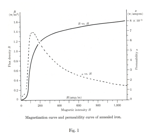
Magnetization curve. A graph of B vs. H is called the magnetization curve of a material. A magnetization curve and permeability curve for annealed iron is shown in Fig. 1. It can be seen that permeability is not a constant. Since μ = B/H, the permeability curve can be computed from the magnetization curve.
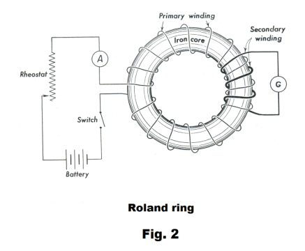
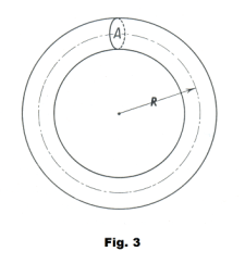
Measurement of magnetic permeability using a Rowland ring. We now discuss the method of measuring the permeability of some chosen material using a Roland ring. First a specimen of the material whose permeability is desired is machined in the form of a ring and then wound with a closely spaced toroidal coil. This coil-wrapped ring is called a Rowland ring, named after J. H. Rowland who made much use of it in his experimental work in electricity and magnetism. The winding of wire around the ring is called the magnetizing winding and the current in the winding is called the magnetizing current. This coil-wrapped ring is connected in series with a battery, rheostat, ammeter and switch. Then a small secondary coil is wound around the toroid and connected to a ballistic galvanometer as shown in Fig. 2. The method of determining the permeability of a material is to first derive the magnetization curve for the material and from that to compute a permeability curve. We obtain the magnetization curve as follows: We start with an unmagnetized piece of the material and vary the current through the toroid in a series of small steps. At each step the value of H can be computed from 15) above. Each time the current is changed, there is a corresponding change in the flux density B and, consequently, a change in flux through the secondary coil. From Faraday’s law, an emf will be induced in the secondary coil.
Let A represent the cross-sectional area of the toroid. See Fig. 3. Since at any point in time the flux within the toroid is given by Φ = AB, a change in current will cause a change in flux in the toroid of
18) ΔΦ = A ΔB
This change of flux in the toroid will cause an induced emf in the secondary coil of
![]()
where n is the number of turns in the secondary coil.
If the total resistance of the secondary coil and the galvanometer is R, the magnitude of the current induced in the secondary coil is
![]()
Since Δq = i Δt, we have
![]()
or

We can use this equation to compute ΔB. The maximum deflection of the ballistic galvanometer is proportional to the quantity of charge q that passed through it. If we know the proportionality constant, we can determine Δq, and from Δq we can compute ΔB. Thus for each increase in current, we can compute H from eq. 15) and ΔB from eq. 22). Using this procedure we can construct a graph of B vs. H for the material and from that graph we can compute a permeability curve.
Hysteresis. Let us take a piece of unmagnetized iron in the form of a ring, wind a toroid around it, and use the above procedure to plot a graph of B vs. H. If we do this the graph will follow the magnetization curve OA shown in Fig. 4 (a). It will increase rapidly at first, then more slowly, and flatten out at A. Along the flat portion of the curve, the iron is said to be saturated. Now let us decrease the current in small steps and plot the curve. We will find that this curve will not retrace the original curve OA, but will instead follow the curve AC. When the current has been reduced to zero, there will be an amount of residual magnetism still in the
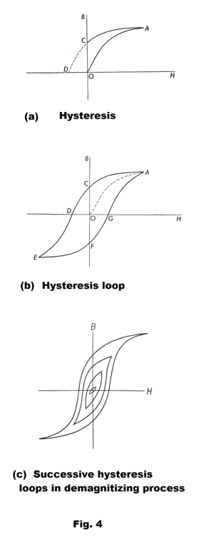
iron given by OC. The iron is now permanently magnetized and the amount OC of magnetic induction B remaining in it is called the retentivity. In some applications, such as in permanent magnets, it is desirable to have a high retentivity. In other applications, it is desirable to have a low retentivity.
To reduce the magnetic induction to zero in our iron ring, to demagnetize it, we must reverse the current in the magnetizing coil. This changes the sign of H and when H has reached the negative value given by OD, the magnetic induction within the iron will have been reduced to zero. The value of H needed to reduce B to zero is called the coercive force.
This phenomenon in which B lags behind when H returns to its previous value is called hysteresis. The word hysteresis means “to lag behind”.
All ferromagnetic materials exhibit the phenomenon of hysteresis. As a consequence, the value of B for a given value of H depends on the magnetic history of the material.
If an alternating current is sent through a toroid wound on a ferromagnetic core, the B-H curve will be similar to that shown in Fig. 4 (b). It is called a hysteresis loop. In many pieces of electrical equipment, such as transformers and motors, masses of iron are located in magnetic fields whose direction is continually reversing. As the value of H cycles, increasing to a maximum in one direction, decreasing to zero, going to the same maximum in the opposite direction, etc. the induction B traces out a hysteresis loop. One consequence is the production of heat. Heat is produced within the material each time it is caused to go through the hysteresis loop. It can be shown that the heat developed per unit volume, in each cycle, is proportional to the area enclosed in the hysteresis loop. It is thus desirable that the hysteresis loop of the material be as narrow as possible to minimize heat loss.
Demagnetizing materials. How does one demagnitize a magnetized material? One simple way is to place it inside a coil and pass alternating current through the coil, slowly reducing the amplitude of the current so that the hysteresis loop gets smaller and smaller with successive cycles, as shown in Fig. 4 (c). When the current reaches zero, the values of B and H are zero.
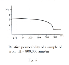
The Curie temperature. The permeability of ferromagnetic materials decreases with increasing temperature, and the relative permeability falls to close to one at a temperature (different for different materials) called the Curie temperature. Iron is paramagnetic above the Curie temperature. Fig. 5 shows a graph of the relative permeability of a sample of iron at different temperatures.
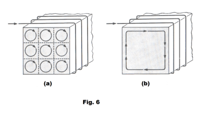
Ampere’s theory of magnetism. The earliest speculation in regard to the cause of magnetism in lodestones or permanent magnets was that this kind of substance contained tiny particles each of which possessed two magnetic poles and that the process of magnetizing a body consisted in aligning these particles so that their like poles pointed in the same direction. When it was discovered that magnetic effects could be produced by currents, Ampere proposed the idea that the magnetic properties of a substance might arise from a multitude of tiny closed current loops within the substance. The idea assumed that the current in the loops flowed indefinitely with no resistance. In an unmagnetized body the loops were oriented at random. The magnetizing process consisted in aligning these loops so that their planes were all parallel to each other and with the currents all circulating in the same direction. See Fig. 6 (a). At the time the idea seemed highly speculative since currents that would continue indefinitely without resistance seemed unlikely. Now we think the theory is essentially correct with the elementary current loops consisting of electrons spinning about their axes or orbiting nuclei.
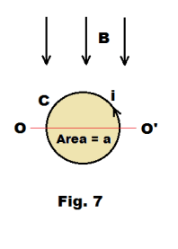
Fig. 6 (a) is a pictorial representation of a body containing a multitude of tiny current loops all so oriented that their planes are all parallel to each other and with the currents all circulating in the same direction. At interior points of the body the currents in adjacent loops are in opposite directions and their magnetic effects cancel. The outer portions of the outside loops, however, are uncompensated and the entire assembly of loops is equivalent to a current circulating around the outside of the conductor as shown in Fig. 6 (b). The effect of this circulation of current around the outside of the conductor would be the same as that of a current moving through the coils of a solenoid, creating a north and south pole. If this type of phenomenon occurs in the iron of the iron core of a toroid under a magnetizing current, it could account for the fact that the magnetic flux density B is so much greater in a toroid with an iron core than it is in a toroid with an air core.
Torque on a bar magnet. Fig. 7 shows a closed loop C of wire carrying a current i in a magnetic field B. If the area enclosed by the loop is a and the plane of the loop is parallel to the field B, the magnetic field will exert a torque τ on the loop of
23) τ = Bia
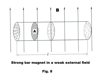
about axis OO'. Fig. 8 shows a strong bar magnet of length l and cross-section A placed perpendicular to a weak external field B. The small circles shown in the cross-sections represent tiny current loops envisioned as occurring in the bar. Assume that all of these current loops are aligned with their planes parallel to the field and that the currents within the loops are all circulating in the same direction. Furthermore, assume that the area enclosed by each current loop is a and that there are n loops per unit volume. The magnetic field will exert a torque on each current loop of
24) τ = Bia
There will be a total of nAl such loops in the bar so the torque placed on the bar from all of the loops will be
25) τ = (Bia)∙(nAl)
or
26) τ = B∙(ianA)∙l
The quantity “ianA” is of great importance.
■ The quantity “ia” (current times area) is called the magnetic moment of a current loop.
■ The quantity “ian” is the magnetic moment per unit volume, or intensity of magnetization.
■ The quantity “ianA” is the pole strength p of the two poles of the bar.
27) p = ianA
Thus, the torque exerted on the bar is
28) τ = Bpl
Since pl = (ian)∙(Al) = magnetic moment per unit volume × volume of magnet, pl represents the total magnetic moment of the magnet. We represent the quantity pl by m
29) m = pl = (ian)∙(Al)
where m is the magnetic moment of the magnet.
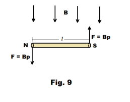
In the equation τ = Bpl of 28) the product Bp represents the force F that the magnetic field B exerts on each of the two poles of the magnet. See Fig. 9. Since the poles are separated by the distance l, the torque on the magnet is given by τ = Fl = Bpl.
Thus we can consider the torque in two ways:
(1) due to electronic loop currents and computed from
τ = B∙(ianA)∙l
(2) due to forces exerted by the field on the poles of the magnet and computed from
τ = Bpl
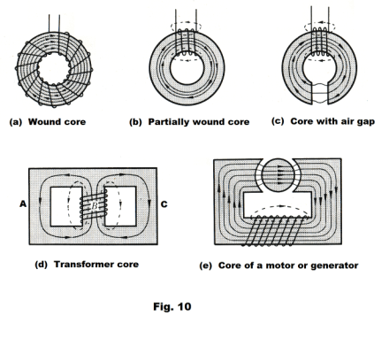
The magnetic circuit. A magnetic circuit is a closed path or paths, usually in the form of a ferromagnetic material such as soft iron, through which magnetic flux flows. The path may include air gaps and other materials. Fig. 10 shows some examples of magnetic circuits. There are some similarities between these flux paths and electric circuits, accounting for the name, although nothing flows in a magnetic circuit.
In a toroid the flux density B is given by
![]()
and since Φ = BA
![]()
or

The resistance of a conductor of length l is given by
![]()
where ρ is the resistivity and A is the cross-sectional area. In terms of conductivity σ (σ = 1/ρ), this formula is

Ohm’s law can then be written as
![]()
Now the form of 32) is the same as that of 35) with Φ corresponding to the current I, the quantity nI corresponding to emf, and l/μA corresponding to the resistance l/σA. The numerator of 32) is called the magnetomotive force and the denominator is called the reluctance of the magnetic circuit i.e.
36) Magnetomotive force (mmf) = nI
37) Reluctance (R) = l/μA
where
I = current
n = number of turns
l = length
μ = permeability
A = cross-sectional area
Thus 32) can be written

which is the magnetic circuit counterpart of Ohm’s law.
Magnetomotive is expressed in ampere turns and reluctance is expressed in ampere-turns per weber.
The usefulness of the equation Φ = mmf/R is best appreciated in connection with a circuit containing an air gap, or more generally, any circuit composed of sections of different permeabilities, lengths, and cross-sections. It happens that the equivalent reluctance of such a circuit is given by the same laws as the equivalent resistance in a network of conductors. For example, a ring containing an air gap can be viewed as two resistors in series and the equivalent reluctance of the circuit is the sum of the reluctances of the ring and the air gap. The arms A and C of the transformer core of Fig. 10 (d) can be viewed as resistors in parallel and the reciprocal of their equivalent resistance is the sum of the reciprocals of the arms individually. Thus a magnetic circuit can be viewed as a succession of resistances (reluctances) and the resistance laws that obtain are the same as those for electrical circuits.
Reluctances in series. The equivalent reluctance R of n reluctances R1, R2, ... , Rn connected in series is given by
39) R = R1 + R2 + ... + Rn
where each reluctance Ri is given by the formula Ri = li /μiAi.
Reluctances in parallel. The equivalent reluctance R of n reluctances R1, R2, ... , Rn connected in parallel is given by

Thus for a simple series circuit one has

References
1. Sears, Zemansky. University Physics
2. Semat, Katz. Physics.
Jesus Christ and His Teachings
Way of enlightenment, wisdom, and understanding
America, a corrupt, depraved, shameless country
On integrity and the lack of it
The test of a person's Christianity is what he is
Ninety five percent of the problems that most people have come from personal foolishness
Liberalism, socialism and the modern welfare state
The desire to harm, a motivation for conduct
On Self-sufficient Country Living, Homesteading
Topically Arranged Proverbs, Precepts, Quotations. Common Sayings. Poor Richard's Almanac.
Theory on the Formation of Character
People are like radio tuners --- they pick out and listen to one wavelength and ignore the rest
Cause of Character Traits --- According to Aristotle
We are what we eat --- living under the discipline of a diet
Avoiding problems and trouble in life
Role of habit in formation of character
Personal attributes of the true Christian
What determines a person's character?
Love of God and love of virtue are closely united
Intellectual disparities among people and the power in good habits
Tools of Satan. Tactics and Tricks used by the Devil.
The Natural Way -- The Unnatural Way
Wisdom, Reason and Virtue are closely related
Knowledge is one thing, wisdom is another
My views on Christianity in America
The most important thing in life is understanding
We are all examples --- for good or for bad
Television --- spiritual poison
The Prime Mover that decides "What We Are"
Where do our outlooks, attitudes and values come from?
Sin is serious business. The punishment for it is real. Hell is real.
Self-imposed discipline and regimentation
Achieving happiness in life --- a matter of the right strategies
Self-control, self-restraint, self-discipline basic to so much in life