Website owner: James Miller
Circuits. Power. Equivalent resistance in series and parallel circuits. Wheatstone bridge. Terminal voltage of a battery. Kirchhoff’s rules. The potentiometer.

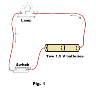
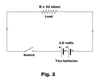
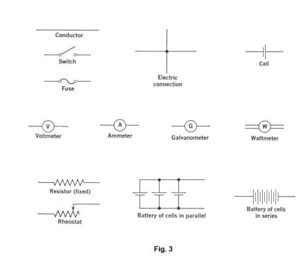
Circuit diagrams. Fig. 1 shows an electrical circuit containing two 1.5 volt batteries, a lamp and a switch in which the current in the form of electrons flow from the negative to the positive terminal of the batteries. Fig. 2 shows a schematic wiring diagram of the circuit. Some of the conventional symbols used in schematic wiring diagrams are shown in Fig. 3.
Convention on the direction of flow of current. Electrons flow from the negative terminal to the positive terminal and thus current flow is from the negative terminal to the positive terminal. The negative terminal is the high potential terminal and the positive terminal is the low potential terminal. However, for many years just what electric current was was not known; it was not realized that electric current consisted in the flow of electrons. For many years it was assumed that electric current flowed from the positive terminal to the negative terminal (opposite from the way it really flows), the positive terminal being the high potential terminal and the negative terminal being the low potential terminal. Flow from the positive terminal to the negative terminal became the accepted convention. Most authors use the old convention and assume that current runs from the positive terminal to the negative terminal, even though it doesn’t. We will henceforth go with convention and assume that electric current flows from the positive terminal to the negative terminal.
Potential energy drops in a circuit. A 50 lb steel ball sitting on top of a 100 foot tower has 5000 ft-lbs of potential energy relative to the ground. If it is dropped, that potential energy is transformed to kinetic energy and, on hitting the ground, there is no potential energy left — it has all been transformed to another type of energy. In a similar way, a one coulomb test charge moving from the high potential terminal of a battery to the low potential terminal by way of a wire conductor does work and gives up its potential energy as it passes through the circuit. If the circuit contains resistances R1, R2, ... , Rn, it does work in passing through each of the resistances. When it has passed through the last resistance, all work has been done, and all the potential energy has been used up. Let Va be the voltage of the high potential terminal and Vb be the voltage of the low potential terminal. Then as the charge makes its way from the high potential terminal to the low potential terminal, its potential energy will drop from Va volts to Vb volts. If we attach one lead of a voltmeter to the high potential terminal and check the voltage drop at different points along the circuit, we will see that the voltage has dropped down to Vb at the end of the circuit.
Work done by a moving charge. The work W done, in joules, when a charge of q coulombs moves through a potential difference of Vab volts in a circuit is
1) W = qVab
Power. The power, or rate at which work is done over a potential drop of Vab in a circuit, is
![]()
**********************
Derivation. From 1)
3) dW = Vab dq
Now
4) i = dq/dt
Substituting 4) into 3) gives
5) dW/dt = i Vab
**********************
Special case when the circuit between points a and b is pure resistance. In the special case when the circuit between points a and b is pure resistance, all of the energy is converted to heat and the power represents the rate at which heat is generated. Here the rate at which heat H is generated is given by

where P is in joules/ sec, i is in amps, V is in volts, and R is in ohms.
Since 1 joule = 0.239 calories, the heat H in calories generated in time t is
7) H = 0.239 i2Rt
Series and parallel connections. An electric circuit may be very simple and consist of one or two electrical devices connected to a power source or it may be very complex and consist of a large number of circuit elements such as multiple emf’s, resistors, capacitors, motors, etc. all connected in more or less complicated ways. A complex circuit is called a network.
Fig. 4 illustrates four different ways in which three resistors having resistances R1, R2 and R3 might be connected between the two points a and b.
Series connection. In Fig. 4 (a), the three resistors are said to be connected in series between
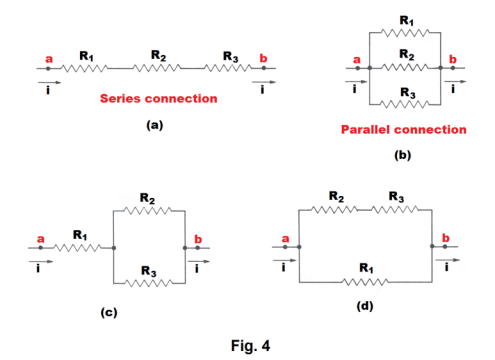
points a and b. There is only one path between the two points a and b and the resistors are on that path. Any number of circuit elements such as resistors, cells, motors, etc. are said to be connected in series with one another if they are connected as the resistors in Fig. 4 (a), all being on a single path between points a and b.
Parallel connection. In Fig. 4 (b) the three resistors are said to be connected in parallel between points a and b. Each resistor is on a separate path between points a and b. Any number of circuit elements similarly connected are said to be connected in parallel with one another.
In Fig. 4 (c), resistors R2 and R3 are connected in parallel and this combination is in series with resistor R1. In Fig. 4 (d), resistors R2 and R3 are in series and this combination is in parallel with R1.
Equivalent resistance. Suppose we have some combination of resistances (combinations such as those illustrated in the four examples of Fig. 4) situated between two points a and b in a circuit. It is always possible to find a single resistor that will replace the combination and leave unchanged both 1) the potential difference Vab between the points a and b, and 2) the line current i at points a and b. The resistance of this single resistor is called the equivalent resistance of the combination. For example, if any one of the combinations in Fig. 4 were replaced by its equivalent resistance R, we could write Vab = Ri where Vab is the potential difference between a and b and i is the line current at points a and b.
Rules for resistors connected in series. For a set of resistors connected in series:
1. The equivalent resistance R of n resistors R1, R2, ... , Rn connected in series is given by
8) R = R1 + R2 + ... + Rn
Thus the equivalent resistance of any number of resistors in series is the sum of their individual resistances.
2. The current in all parts of a series circuit is the same.
3. The total potential drop across several resistors in a series circuit is equal to the sum of the potential drops across the separate resistors.
Def. Conductance. The conductance G of a conductor is defined as the reciprocal of its resistance R:
G = 1/R
The unit of conductance is mhos.
Rules for resistors connected in parallel. For a set of resistors connected in parallel:
1. The equivalent resistance R of n resistors R1, R2, ... , Rn connected in parallel is given by

Thus the total conductance of a set of resistors is equal to the sum of their conductances.
2. The total current in the circuit [i.e. the line current at points a and b in Fig. 4 (b)] equals the sum of the currents in the separate branches.
3. The potential drop across several resistors connected in parallel is the same across all branches i.e. the potential difference is the same from point a to point b of Fig. 4 (b), whatever the route.
Problem. Compute the current I through the battery in Fig. 5.
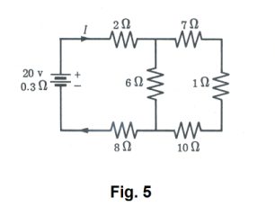
Solution. The 7, 1 and 10 ohms are in series and their joint resistance is 18 ohms. This 18 ohms is in parallel with 6 ohms and the equivalent resistance R1 is given by

Solving gives R1 = 4.5 ohms
The equivalent resistance for the entire circuit is R = 4.5 + 2 + 8 + 0.3 = 14.8 ohms and the battery current is I =V/R = 20/14.8 = 1.35 amp
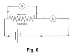
Measurement of potential differences and current using the voltmeter and ammeter. To measure a voltage drop VAB between points A and B in a circuit, the voltmeter is connected in parallel as shown in Fig. 6. To measure the current in a circuit, the ammeter is connected in series as shown in the figure. An ammeter is a very low resistance device and a voltmeter is a very high resistance device to ensure best accuracy. If very accurate measurements are required, the resistances of the ammeter and voltmeter must be considered part of the circuit.
Measurement of resistance. We can measure the resistance of a conductor by measuring the potential drop over the conductor with a voltmeter and measuring the current flowing through the conductor with an ammeter as shown in Fig. 6. One then uses Ohm’s law, R = V/ I, to compute the resistance. A much more accurate method involves using the Wheatstone bridge.
Wheatstone bridge method of measuring the resistance of a conductor. The Wheatstone bridge consists of a board a little over a meter in length and about 15 centimeters wide with heavy brass strips mounted along the top and at each end. See Fig. 7. A meter stick is mounted along the bottom with a heavy wire AB of uniform resistance, one meter long, stretched over it as shown in the figure. At the top left are terminals for attaching a resistor of unknown resistance and in the top right are terminals for connecting a resistor of known resistance. One lead of a galvanometer is connected to a terminal at the midpoint of the top brass strip and the other lead is connected to a contact key that slides along the wire on top of the meter stick. (A galvanometer is a very sensitive instrument that measures small currents and indicates their direction of flow.)
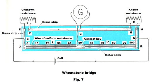
Operation of the Wheatstone bridge. Current flows from the cell to binding post C where it divides, part taking the path through the unknown and known resistances at the top and part going through the wire AB. The two paths unite at D and the current returns to the cell. In general, some current will also go through the path containing the galvanometer. With known and unknown resistances in place, one makes a measurement by sliding the contact key along the wire until he finds that point at which no current flows through the galvanometer. This is called balancing the bridge. At this point he can compute the value X of the unknown resistance from the relationship
![]()
where L is the meter stick reading in centimeters and L' is 100 - L ( L is the length of the part of the wire from its beginning to the balance point and L' is the length from balance point to end).
A circuit diagram of the Wheatstone bridge is shown in Fig. 8. Here ρ represents the resistance of wire AB in ohms /cm. The bridge will be balanced and no current will flow in path GK when the potential difference between G and K is zero. When this happens the potential difference VCG from C to G is equal to the potential difference VCK from C to K
11) VCG = VGK
and the potential difference VGD from G to D is equal to the potential difference VKD from K to D
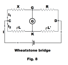
12) VCG = VCK
From 11) and 12) we get
13) I1X = I2ρL
14) I1R = I2ρL'
Dividing 13) by 14) gives
![]()
or

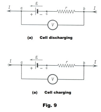
Terminal voltage of a battery or generator. A seat of emf such as a battery or electrical generator will deliver an emf when generating current that is less than its measured terminal voltage when it is not delivering current. This is due to internal resistance which causes internal generation of heat and energy loss when current is flowing. It is customary to represent the internal resistance of a seat of emf by a resistor r which is considered to be in series with a resistanceless source of emf E. Let us find the expressions for the terminal voltage when the cell is discharging and when it is charging.
Case 1. Cell discharging. Fig. 9 (a) depicts the situation when a cell is discharging. We can relate the voltage Va at point a to the voltage Vb at point b by considering the voltage drops and increases as one proceeds from point b to point a. There is a voltage drop at the resistor r and a voltage increase at the cell so
17) Va = Vb - Ir + E
or
18) Va - Vb = E - Ir
Case 2. Cell charging. Fig. 9 (b) depicts the situation when a cell is charging. Considering the voltage drops and increases as one proceeds from point a to point b we obtain
19) Vb = Va - E - Ir
or
20) Va - Vb = E + Ir
In summary, we have
(1) When cell is delivering current (cell discharging):
Terminal voltage = E - Ir
(2) When cell is charging:
Terminal voltage = E + Ir
(3) When no current exists:
Terminal voltage = E
Kirchhoff’s rules. Complicated circuits made up of resistors and sources of emf often cannot be readily resolved into series and parallel combinations of resistors and solved by the method of equivalent resistances. Two rules, first stated by Gustav Robert Kirchhoff (1824 - 1887), enable such problems to be solved systematically.
We first define the terms junction and loop.
Def. Junction. Any point in a network at which three or more conductors are joined.
Def. Loop. Any closed path in an electrical network.
Kirchhoff’s rules are:
Point rule. The algebraic sum of the currents at every junction is zero where a current is regarded as positive if its direction is toward a junction and negative if its direction is away from the junction:
∑i = 0
Loop rule. The algebraic sum of the emf’s in any loop of a network equals the algebraic sum of the Ri products in the same loop:
∑E = ∑Ri
Procedure for solving networks using Kirchhoff’s rules.
Step 1. Assign an algebraic symbol (e.g. i1, i2, ..) and direction to all unknown currents and all unknown emf’s. The assumed directions are completely arbitrary. Assign algebraic symbols (e.g. R1, R2, ..) to all unknown resistances.
Note. The solution is carried through on the basis of the assumed directions. If, in the solution of the equations, a negative value is obtained for a current or emf, its correct direction is opposite to that assumed.
Step 2. Create a circuit diagram with all known and unknown quantities and directions shown.
Step 3. Assign letters (e.g. a, b ,c ...) to all junctions.
Step 4. Form the junction equations using the point rule. If there are n junctions, form junction equations for any n-1 of the junctions. (Application of the point rule at the n-th junction won’t lead to an independent relation.)
Step 5. Imagine the network to be broken up into a number of simple loops, like pieces of a jigsaw puzzle. Make sure every circuit element is included in at least one loop. Apply the loop equation to each of the loops.
When applying the loop rule, some direction around the loop (i.e. clockwise or counterclockwise) must be chosen as the positive direction. All currents and emf’s in this direction are regarded as positive, all in the opposite direction are regarded as negative.
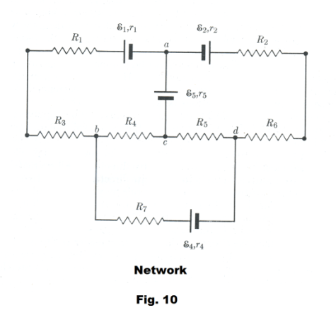
Problem. Given the network shown in Fig. 10 where the indicated emf’s E1, E2, ... and resistances R1, R2, ... are assumed to be known quantities. Write the junction equations and loop equations.
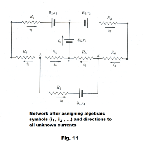
Solution. First we need to assign algebraic symbols and directions to all currents. Fig. 11 shows the assignment we have made.
Letters have been assigned to the various junctions. There are four junctions: a, b, c, and d.
We now form the junction equations:
Junction a: i1 + i2 - i3 = 0
Junction b: -i1 - i4 - i6 = 0
Junction c: i4 + i5 - i2 = 0
Let us now break the network up into loops and form the loop equations. We will consider the clockwise direction positive for each loop. The loop equations are:
1] -E1 - E5 = i1R1 + i1r1 - i2r5 - i4R4 + i1R3
2] E2 + E5 = i3r2 + i3R2 + i3R6 + i5R5 + i2r5
3] E4 = i4R4 - i5R5 - i6r4 - i6R7
We now have six independent equations to be solved for six unknown currents.
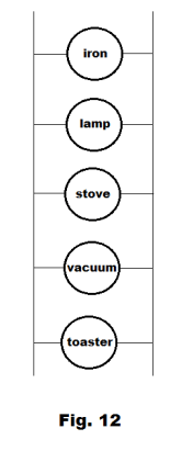
What are the advantages of parallel wiring as opposed to serial wiring? In house wiring, receptacles and appliances are wired in parallel. See Fig. 12. Why? One must consider that everything in a series circuit receives the same amount of current. In parallel wiring this isn’t the case. In parallel wiring each appliance will receive whatever current it requires. An electric light draws a different amount of current than a stove. It needs to be on its own circuit.
The potentiometer. The potentiometer is an instrument that is used to measure the emf of a seat of emf (such as a cell) without drawing any current from the seat. If a voltmeter is used for this purpose, the reading will be less than the emf because the voltmeter draws current from the seat of emf and the reading includes the voltage drop due to the internal resistance of the seat.
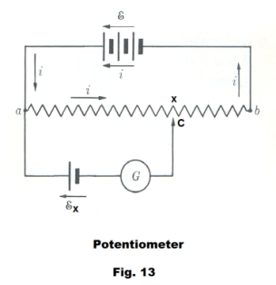
A schematic diagram of a potentiometer is shown in Fig. 13. In the upper loop of the figure, a resistance wire ab of uniform resistance is connected to a cell of emf E. In the lower loop, a cell X of unknown emf, whose emf Ex is to be measured, is connected in series with a galvanometer and a sliding contact C. Determining the value of an unknown emf Ex involves moving the contact C to a position where there is no current flowing through the galvanometer. Assume that at the point where no current is flowing, the contact C is at the value C = x. We can then write
(upper loop) Vax = iRax
(lower loop) Vax = Ex
i.e. when no current is flowing through the galvanometer
21) Ex = iRax
In order to use a potentiometer it is necessary to first calibrate it with the aid of a standard cell such as the Weston normal cell whose emf has previously been determined. Let us replace the cell X of unknown resistance with our standard cell WS with emf ES and let us move contact C so as to determine the balance point of no current. Assume it occurs at the point C = s. Then we have
22) ES = iRas
Dividing 21) by 22) gives
23) Ex = ES (Rax/Ras)
If ls is the length of the slide wire from a to s and lx is the length of the slide wire from a to x, then
24) Rax/Ras = lx / ls
Substituting 24) into 23) gives
25) Ex = ES (lx / ls)
The measurement of the emf has thus been reduced to the measurement of two lengths along a uniform slide wire.
References
1. Dull, Metcalfe, Brooks. Modern Physics.
2. Sears, Zemansky. University Physics
3. Semat, Katz. Physics.
4. Freeman. Physics Made Simple.
Jesus Christ and His Teachings
Way of enlightenment, wisdom, and understanding
America, a corrupt, depraved, shameless country
On integrity and the lack of it
The test of a person's Christianity is what he is
Ninety five percent of the problems that most people have come from personal foolishness
Liberalism, socialism and the modern welfare state
The desire to harm, a motivation for conduct
On Self-sufficient Country Living, Homesteading
Topically Arranged Proverbs, Precepts, Quotations. Common Sayings. Poor Richard's Almanac.
Theory on the Formation of Character
People are like radio tuners --- they pick out and listen to one wavelength and ignore the rest
Cause of Character Traits --- According to Aristotle
We are what we eat --- living under the discipline of a diet
Avoiding problems and trouble in life
Role of habit in formation of character
Personal attributes of the true Christian
What determines a person's character?
Love of God and love of virtue are closely united
Intellectual disparities among people and the power in good habits
Tools of Satan. Tactics and Tricks used by the Devil.
The Natural Way -- The Unnatural Way
Wisdom, Reason and Virtue are closely related
Knowledge is one thing, wisdom is another
My views on Christianity in America
The most important thing in life is understanding
We are all examples --- for good or for bad
Television --- spiritual poison
The Prime Mover that decides "What We Are"
Where do our outlooks, attitudes and values come from?
Sin is serious business. The punishment for it is real. Hell is real.
Self-imposed discipline and regimentation
Achieving happiness in life --- a matter of the right strategies
Self-control, self-restraint, self-discipline basic to so much in life