Website owner: James Miller
Electronics. Vacuum tube. Thermionic emission. Diode. Triode. Rectifiers. Cathode heaters. Triode oscillator. Semiconductor diodes. Transistors. Cathode-ray tube. X-ray tube. Electron microscope. Photocell. Dielectric, induction heating. Neon and fluorescent lamps.

In this section we shall assume, for clarity of explanation, that current flows in the direction that electrons actually do flow: from negative to positive (instead of the conventional direction of from positive to negative).
The vacuum tube. The vacuum tube has been called the most important electrical device introduced in the twentieth century. It has given rise to the field of electronics, making possible radio, long-distance telephone, sound motion pictures, television, radar, electronic computers, etc.
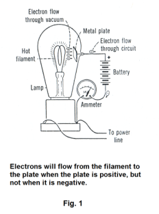
The Edison effect. In 1883 Edison, in the course of conducting experiments to improve the electric light bulb, had a glass-blower seal a metal plate inside a light bulb as shown in Fig. 1. The bulb was exhausted and the filament heated as usual. Edison discovered that when he connected the plate to a battery and ammeter as shown, a current flowed. No current flowed, however, when he reversed the battery connections, connecting the plate to the negative terminal. Edison made note of the fact, had no explanation for it, and made no further investigation. He simply continued with his work on improving the light bulb. Other researchers replicated the experiment and wondered of what practical use it might be and one by one concluded that it was just a scientific curiosity. What Edison had discovered here, however, was the fundamental mechanism of the vacuum tube. Several years later Sir J. J. Thomson discovered the electron and with the discovery of the electron came the electron theory of electricity and that theory gave the explanation: Connecting the plate to the positive terminal made the plate positive. Electrons “boiled off” the heated carbon filament creating a cloud of electrons (called a space charge) outside the filament in a phenomenon called thermionic emission. Electrons in this electron cloud were attracted to the positive plate and swarmed across the evacuated space to the plate. From there they passed around the circuit creating an electrical current. Connecting the plate to the negative terminal made the plate negative and the electrons in the electron cloud were repelled by the plate and no current flowed.
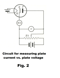
The diode. The diode is the simplest type of vacuum tube with only two electrodes, a cathode and an anode. A schematic diagram of a diode is shown in Fig. 2 where K is the cathode, P is the plate (anode) and H is the heater. The cathode is often in the form of a hollow cylinder heated by a fine resistance wire within it. The plate is a larger cylinder surrounding the cathode and coaxial with it. Electrons emitted from the outer surface of the cathode are attracted to the plate and plate current is read on the milliammeter MA. The potential difference between plate and cathode is controlled by the slide wire and read on the voltmeter.
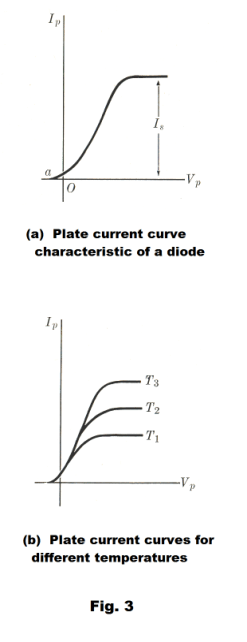
If the potential difference between the cathode and plate is small (a few volts) only a few electrons reach the plate, the most penetrating only a small distance into the cloud of space charge and then returning back to the cathode. As the plate potential is increased, more and more electrons are attracted to it, and with sufficiently high potentials, (on the order of a hundred volts) all of the emitted electrons arrive at the plate. Further increase of the plate potential does not increase the plate current and the current is said to be saturated.
A graph of plate current, Ip, vs. plate potential, Vp, is shown in Fig. 3. Note that Ip is not zero even when Vp is zero. This is because the electrons leave the cathode with an initial velocity and some penetrate the electron cloud and reach the plate even with no accelerating field.
The saturation current Is shown in Fig. 3 (a) is equal to the current from the cathode and for a given tube its magnitude depends markedly on the cathode temperature, increasing with increasing temperature. Fig. 3 (b) shows plate current curves for three different cathode temperatures, T1, T2, and T3.
The relationship between the saturation current and temperature is given by
![]()
where Js is the saturation current density at the cathode surface, A is a constant characteristic of the emitting surface, T is the Kelvin temperature of the emitter, k is the Boltzmann constant, and f is the work function of the surface, a quantity related to the energy required for an electron to leave the surface.
The work function can be reduced substantially by the presence of impurities. For example, a small amount of thorium can reduce the work function of pure tungsten by around 50%. Since the smaller the work function the larger the current density for a given temperature, most vacuum tubes use cathodes having composite surfaces.
Cathode heaters. In some vacuum tubes the heated filament gives off the electrons and the filament and cathode are one. In most vacuum tubes, however, the source of heat is separate from the cathode. The source of heat is a coiled filament of tungsten wire, called the heater, inside a spaghetti-like ceramic rod. Around the ceramic is the cathode, a metal sleeve covered with a coating of rare-earth elements. When heated, the oxide coating gives off electrons much more efficiently than a bare wire itself. The cathode has its own lead and is not connected to the heating current leads.
Gas-filled diodes. In some diodes, after the air has been pumped out of the tube, a small amount of a gas such as mercury vapor, argon, neon, helium, or xenon is pumped into the tube. The reason for doing this is that it can result in substantially increased current flow in the tube. The explanation for the effect is ionization of the molecules. Electrons traveling at high velocities collide with the gas molecules causing them to split up into ions.
Rectifiers. A rectifier is an electrical device that converts alternating current, which periodically reverses direction, to direct current, which flows in only one direction. The process is known as rectification.
Rectifiers take a number of forms. They include vacuum tube diodes, mercury-arc valves, ignitrons, copper and selenium oxide rectifiers, semiconductor diodes, silicon-controlled rectifiers and other silicon-based semiconductor switches. In the past, synchronous electromechanical switches and motors have been used. Early radio receivers, called crystal radios, used a "cat's whisker" of fine wire pressing on a crystal of galena (lead sulfide) to serve as a point-contact rectifier or "crystal detector" in rectifying the incoming AC signal.
Rectifiers have many uses, but often serve as components of DC power supplies and high-voltage direct current power transmission systems. Rectification may be used in roles other than to generate direct current for use as a source of power. Rectifiers are used in the detection of radio signals.
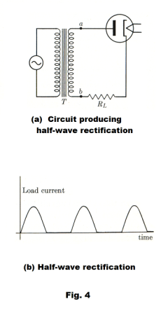
Because of the alternating nature of the input AC sine wave, the process of rectification alone produces a direct current that, though unidirectional, consists of pulses of current. Many applications of rectifiers, such as power supplies for radio, television and computer equipment, require a steady direct current, such as would be produced by a battery. In these applications the output of the rectifier is smoothed by an electronic filter to produce a steady current.
The circuit shown in Fig. 4 is commonly used to rectify half of the alternating current cycle, that is, to produce half-wave amplification. During the half-cycle when the plate is positive with respect to the cathode a current exists in load RL. During the following half-cycle no current exists. See Fig. 4 (b).
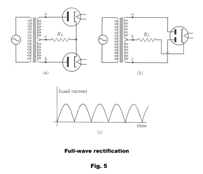
To obtain full-wave rectification one can use two separate diodes as shown in Fig. 5 (a), or what amounts to the same thing, a vacuum tube with two plates as shown in Fig. 5 (b). The secondary of the transformer is tapped at the center c, giving rise to two alternating potential differences Vac and Vbc which are 180o out of phase. During one half-cycle one tube conducts and the other one doesn’t. On the next cycle the second tube conducts and the first doesn’t, giving a current in load RL during each half-cycle as shown in Fig. 5 (c).
The triode. Although diodes are useful in rectifying alternating current, they could not alone have made radio and all the newer electronic developments possible. What was needed was a way to boost the strength of weak radio signals. In 1906 Lee DeForest achieved this amplifying action by placing another electrode between the cathode and the plate.
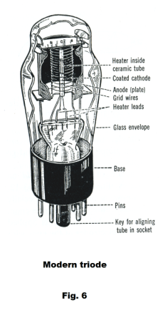
The new electrode was a grid or helix of fine wire and was termed the grid. A cut-away view of a modern triode is shown in Fig. 6.
The addition of a grid greatly increases the uses to which vacuum tubes can be put. The grid provides an easy way of controlling the electron flow from the cathode to the plate.
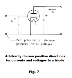
The schematic symbol for a triode is shown in Fig. 7 where a dashed line represents the grid. Both grid voltage ec and plate voltage eb are given with respect to the cathode voltage as a zero reference. Thus a grid voltage of ec = 10 volts is a voltage of 10 volts above the cathode voltage. A plate voltage of eb = 30 volts is 30 volts above the cathode voltage.
In general, small changes in grid voltage produce large changes in plate current. When the grid voltage is positive, it helps pull electrons from the cathode towards the plate. Some electrons will hit the grid but most will pass through the grid and go on to the plate. When the grid is negative it repels the electrons back to the cathode and retards current flow. Even when the plate is highly positive, it takes only a small negative charge on the grid to block the electrons because the grid is so much closer to the cathode. The graph of Fig. 8 gives an idea of what happens to plate current when we vary the grid voltage. When the grid voltage is highly negative, as at point a, the plate current is zero because all of the electrons are blocked by the grid. As the grid voltage is increased we reach point b where a few electrons get through the grid to form a small plate current. Increasing the grid voltage still more causes the plate current to increase rapidly, as at c and d. When the grid voltage increases above zero, it is aiding the plate in propelling the electrons toward the plate. There is then a tapering effect and at point f the plate current reaches a maximum. Further increases in grid voltage have no effect on plate current.
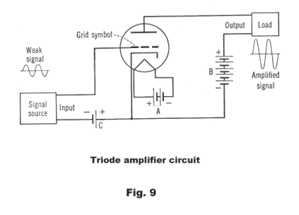
In using the triode to amplify we wish to operate in the section of the curve between c and d where the relationship between grid voltage and plate voltage is linear so as to not introduce distortion into the amplified signal. To do this the grid is operated at a
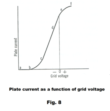
small negative voltage called the grid bias , ec = -E. A triode amplifier circuit is shown in Fig. 9. The A battery provides the current for the heater. The B battery serves the plate and maintains a positive charge on it. The C battery serves the grid and, when there is no input signal, maintains it at a constant negative bias of ec = -E. As a consequence, the grid bias voltage is sometimes called the C bias. With these three batteries, the triode is able to boost the strength of a weak input signal so that a much stronger signal is sent to the load. The output signal has exactly the same waveform as the input signal since we get amplification without distortion as long as we remain in the linear part of the plate current curve. If the sinusoidally alternating input voltage has an amplitude of ΔE, this input voltage will be superimposed on the constant grid bias -E and the grid voltage will fluctuate between - E - ΔE and - E + ΔE.
Triode oscillator circuit. Fig. 10 shows a simple triode oscillator circuit. The frequency of oscillation of an L-C circuit is

The circuit contains a variable capacitor so the output frequency can be changed by adjusting the capacitor.
In this circuit the oscillations of the L-C portion of the circuit are amplified by the triode and then fed back into the
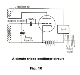
L-C circuit via the feedback coil thus returning energy to the L-C circuit so as to maintain the oscillations which would otherwise die out.
This type of oscillator has been widely used in superheterodyne radio and television receivers.
Semiconductor diodes. There are some crystalline materials in which electricity will pass readily in one direction but not in the other. The crystal galena (lead sulfide, PbS) is one. In the early days of radio, galena crystals were used to rectify radio signals.
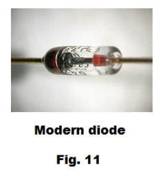
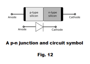
Most modern diodes are made with semiconductor materials such as silicon, germanium, or selenium - usually silicon. See Fig. 11. The cathode, which is negatively charged and has an excess of electrons, is placed adjacent to the anode, which has an inherently positive charge, carrying an excess of holes. At this junction a depletion region forms, with neither holes nor electrons. A positive voltage at the anode makes the depletion region small, and current flows; a negative voltage at the anode makes the depletion region large, preventing current flow.
The junction is called a p-n junction, the p-type material containing an excess of holes and the n-type material containing an excess of electrons. See Fig. 12. The p and n type materials are created by a process called doping that involves adding a small amount of another substance (impurity) to the base material. In general, the substance that is added to the base material to obtain an n-type substance is an element that contains one more valence electron than the base material and the substance that is added to the base material to obtain a p-type substance is an element that contains one less valence electron than the base material. For example, the base material germanium, which has four valence electrons, can be altered by adding a small amount of antimony, which has five valence electrons, to create an n-type material; and a small amount of indium, which has three valence electrons, can be added to germanium to create a p-type material.
Semiconductor diodes are used for rectifying current and have replaced the vacuum tube diode.
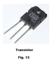
Transistors. A transistor is a semiconductor device used to amplify and switch electronic signals. Transistors come in many shapes and sizes. See Fig. 13 for an example. A transistor has three electrodes and the ability to use a small signal applied between one pair of its terminals to control a much larger signal at another pair of terminals. Its terminals are labeled base, collector, and emitter. A small current at the base terminal (that is, flowing between the base and the emitter) can control or switch a much larger current between the collector and emitter terminals. In amplifying signals a transistor is used in a way similar to that in which a triode vacuum tube is used.
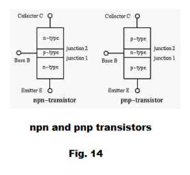
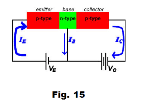
Transistors are constructed of three layers using p-type material and n-type material where the base material is usually silicon. There are pnp transistors and npn transistors. See Fig. 14 and 15.
The transistor has, for most applications, replaced the triode vacuum tube.
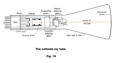
The cathode-ray tube. A cathode-ray tube is a highly evacuated glass tube whose essential features are shown in Fig. 16. Electrons (cathode rays) are emitted by a heated filament K and accelerated toward a fluorescent screen where a small hole in the control grid blocks all but a thin stream. This thin beam is then further focused by the focusing anode. The control grid is maintained at a high negative voltage that can be varied to control the number of electrons that pass through and cut off the beam entirely for black portions of a television picture. The accelerating anode requires a high voltage, often over 10,000 volts for television pictures, to give the electrons enough speed to produce the desired bright spot on the screen. The electrodes up through the accelerating anode are called the electron gun. Out past the electron gun are two pairs of deflecting plates. When voltages are applied to these deflecting plates, the beam is deflected, allowing the beam to be directed to any point on the screen. Thus with varying voltages applied to the deflecting plates, the electron beam can be made to scan the screen line by line.
Def. X-rays. Electromagnetic radiations of extremely short wavelength, emitted from a substance when it is bombarded by a stream of electrons moving in a vacuum at a sufficiently high velocity, as in an electron tube. Their ability to penetrate solids, to ionize gases, and to act on photographic plates has many useful applications, especially in the detection, diagnosis, and treatment of certain organic disorders, chiefly internal. Funk & Wagnalls Dictionary
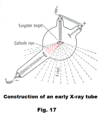
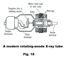
The X-ray tube. X-rays are produced when rapidly moving electrons that have been accelerated through potential differences of tens or hundreds of thousands of volts strike a metal target. The tubes in which they are produced are similar to the cathode-ray tube. If a tungsten or platinum target is placed in a cathode-ray tube in such a position that the electron beam strikes it, X-rays are produced. See Fig. 17. A modern rotating-anode X-ray tube is shown in Fig. 18. The motor armature is inside the tube and the field coils are outside. Rotating the target disc prevents overheating.
X rays, like light and radio waves, are a type of electromagnetic radiation. The only difference is in the wave length. The wavelength is less than one thousandth of the length of the shortest waves of visible light and they are thus invisible. They have many properties similar to light.
X ray properties:
1. They move in straight lines, as does light. This property, along with the property of affecting photographic plates, makes it possible to take pictures with them.
2. They are not affected by magnetic or electrical fields (which shows that they are not charged particles).
3. They can be reflected, refracted, and polarized using mirrors, lenses, and polarizers.
4. They move with the velocity of light.
5. They react with the emulsion of photographic plates in much the same way as light.
6. They can produce fluorescence and phosphorescence, making possible the fluoroscope.
7. They are differentially absorbed by matter. They easily penetrate light elements such as hydrogen, carbon, oxygen, and nitrogen but are absorbed to varying degrees by heavier elements such as iron, calcium, and potassium. As a consequence, when they pass through the human body, the bones appear light against a darker background.
8. A substance will give off X ray spectra when bombarded with cathode rays that are characteristic of the substance. These spectra can be detected by photographic plates.
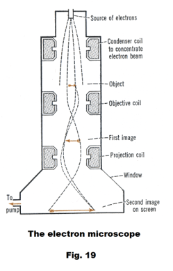
The electron microscope. Fig. 19 shows a diagram of the basic operation of an electron microscope. The electron microscope uses an electron beam instead of light to illuminate a specimen and produce an image. The source of the electrons is thermionic emission from a heated cathode in an electron gun, located at the top of a long, evacuated metal tube. The electron beam is aimed downward and either electrostatic or electromagnetic lenses may be used to focus the beam and form an image. The dashed lines in the figure show the electron paths which are seen to be similar to the paths of light through the lenses of a conventional optical microscope.
An electron microscope can achieve magnifications of up to 10,000,000x whereas ordinary optical microscopes are limited to below 2000x.
The photocell. In the thermionic emission of electrons from metals, the energy needed by an electron to escape from the metal surface is furnished by the energy of thermal agitation.
Electrons can also acquire enough energy to escape from a metal, even at low temperatures, if the metal is illuminated by light of sufficiently short wavelength. The phenomenon is called the photoelectric effect. In fact, many metals emit electrons when light shines on them.
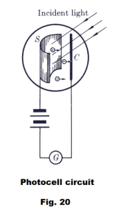
A schematic of a modern phototube is shown in Fig. 20. A beam of light falls on the photosensitive surface S and electrons are emitted by the surface and attracted to the collector C which is maintained at a positive potential with respect to the emitter S. The emitter and collector are enclosed in an evacuated container. The photoelectric current can be read on the galvanometer G.
For any given material as emitter, the wavelength of the incident light must be shorter than some critical value, different for different materials, in order for any photoelectrons to be emitted. This critical wavelength, or corresponding frequency, is called the threshold frequency of the material. The threshold frequency for most metals is in the ultraviolet range but for potassium and caesium oxide it is in the visible range.
As in the case of thermionic emission, the photoelectrons form a cloud of space charge around the emitter. Even with no emf in the external circuit, a few electrons penetrate the cloud of space charge and reach the collector, causing a small current in the circuit.
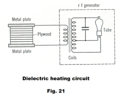
Dielectric heating. Dielectric heating is the heating of dielectric materials such as wood, textiles, plastics, and anything else that doesn’t conduct electricity, by subjecting the material to a high-frequency electromagnetic field. The method is widely employed for heating thermosetting glues, drying lumber and other fibrous materials, preheating plastics before molding, defrosting frozen foods, sterilizing grains and packaged foods, and for fast jelling and drying of foam rubber.
The material to be heated is placed between two metal plates, called electrodes, to which a source of high-frequency energy is connected. See Fig. 21. The resultant heating, in homogeneous materials, occurs throughout the material.
Induction heating. Induction heating is a process for heating metals by subjecting them to a
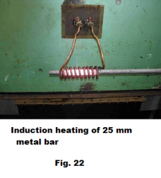
high-frequency electromagnetic field. The same r f generator is used that is used in dielectric heating (see Fig. 21), but instead of the metal plates, a few turns of copper tubing is wrapped around the item to be heated. See Fig. 22. The r-f energy is transferred to any metallic object placed within the turns of tubing. Electrical induction causes the object to heat rapidly by creating eddy currents that flow in circular paths within the object, making it red hot. Water is usually pumped through the tubing to keep it cool and prevent it from melting.
Induction heating is popular for heat-treating metals because it can heat the region to be hardened without heating the rest of the object. One can heat the teeth of a gear, the surface of a shaft, etc. to harden them.
Neon lamps. A neon lamp is an example of a gas discharge tube. A gas discharge tube consists of a glass tube, with an electrode at each end, from which the air has been removed and replaced with some type of gas. When a voltage of about 15,000 volts is applied to the electrodes, ionization of the gas within the tube occurs and an electric discharge occurs with current passing through the tube causing a glow characteristic of the gas. Inert gases like the noble gases neon, argon, krypton or xenon work well, as do carbon dioxide and other gases. If neon gas is used, one gets a bright red light. Mercury vapor in blue glass gives blue light. Mercury vapor in yellow glass gives green light. Helium gives a yellow-white color. The light is created when an atom, excited to higher energy level by a collision, returns back to a lower energy state. The tube does not contain a heater, the high voltage pulling the electrons out of a cold cathode. If the lamp is operated by AC current, each electrode acts as a cathode for half of the AC cycle and as an anode on the other half.
Fluorescent lamps. The fluorescent lamp is a gas discharge tube which has been evacuated and filled with a mixture of mercury and a rare gas (argon, for example) at a very low pressure. In addition, the interior of the tube is coated with a thin layer of fluorescent material called a phosphor. When an electric discharge takes place in the gas mixture, most of the light emitted is in the invisible ultraviolet range. However, when the ultraviolet light strikes the fluorescent layer, the phosphor emits light in the visible range. The light that one sees is thus not the glow of the gas inside the tube but rather the characteristic glow of the fluorescent chemicals in the fluorescent coating. A phosphor is a substance that emits visible light when illuminated by light of a shorter wavelength. Colored glows can be produced by using the right phosphor. Commonly used phosphors are cadmium borate for pink, zinc silicate for green, calcium tungstate for blue and mixtures for white.
The fluorescent lamp employs heaters to supply electrons for starting. As a consequence, it is able to operate on a much lower voltage than the neon lamp.
Sun lamps are essentially fluorescent lamps without the fluorescent coating.
References
1. Sears, Zemansky. University Physics
2. Semat, Katz. Physics.
3. Dull, Metcalfe, Brooks. Modern Physics.
Jesus Christ and His Teachings
Way of enlightenment, wisdom, and understanding
America, a corrupt, depraved, shameless country
On integrity and the lack of it
The test of a person's Christianity is what he is
Ninety five percent of the problems that most people have come from personal foolishness
Liberalism, socialism and the modern welfare state
The desire to harm, a motivation for conduct
On Self-sufficient Country Living, Homesteading
Topically Arranged Proverbs, Precepts, Quotations. Common Sayings. Poor Richard's Almanac.
Theory on the Formation of Character
People are like radio tuners --- they pick out and listen to one wavelength and ignore the rest
Cause of Character Traits --- According to Aristotle
We are what we eat --- living under the discipline of a diet
Avoiding problems and trouble in life
Role of habit in formation of character
Personal attributes of the true Christian
What determines a person's character?
Love of God and love of virtue are closely united
Intellectual disparities among people and the power in good habits
Tools of Satan. Tactics and Tricks used by the Devil.
The Natural Way -- The Unnatural Way
Wisdom, Reason and Virtue are closely related
Knowledge is one thing, wisdom is another
My views on Christianity in America
The most important thing in life is understanding
We are all examples --- for good or for bad
Television --- spiritual poison
The Prime Mover that decides "What We Are"
Where do our outlooks, attitudes and values come from?
Sin is serious business. The punishment for it is real. Hell is real.
Self-imposed discipline and regimentation
Achieving happiness in life --- a matter of the right strategies
Self-control, self-restraint, self-discipline basic to so much in life